

Technical Summary
The Smoke Master Aero Wingtip Smoke System is composed of four primary systems, the Combustion Chamber Assembly, Fuel System Assembly, Smoke Oil System Assembly, and Electrical Control System.
Combustion Chamber
The combustion chamber functions by burning an air-fuel mixture at the front section of the chamber, with oil injected near the midpoint. Ambient air enters the combustion chamber through the front of the wing. Simultaneously, fuel is injected via the fuel nozzle block, mixing with the incoming air before being ignited by a spark plug. The mixture travels through the chamber until combustion is completed, after which two spray nozzles inject oil into the combustion chamber. This oil vaporizes and exits the aft end as a cool, white smoke trail.
The combustion chamber assembly is constructed using both 304 stainless steel and 6061 aluminum materials. The components aft of the combustion head are composed of 304 stainless steel due to its favorable corrosion and heat properties. The combustion head, fuel nozzle block, and air regulator are all composed of aerospace grade aluminum alloys.
For internal wingtip setups, the combustion chamber is cantilevered off of the end rib of the aircraft wing at two mounting locations. The end rib is stiffened with two doublers, one located at each chamber mounting location.

Fuel System
The fuel system requires 100LL or MOGAS to be routed to the combustion chamber. The specific setup is be dependent on the aircraft native fuel system setup. The combustion chamber requires at least 15 psi at 3 gallons per hour at each wingtip. Typically, fuel injected engines are able to support this requirement. If insufficient pressure is available, an additional pump can be installed to boost the fuel pressure.

Oil System
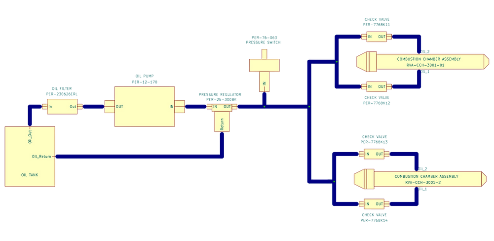
The smoke oil system does not interface with any native aircraft systems. A dedicated oil tank, filter, pressure switch, and pump supply oil to the combustion chambers. The system operates at approximately 100psi and a flow rate of 0.4 gal/hr per combustion chamber (0.8 gal/hr for both wingtips combined). If your aircraft already contains a exhaust smoke system, the same oil tank can be used to supply the wingtip system.
Use of Pure White Smoke by Petroblend is recommended for use in this system.

Electrical Control
The electrical system consists of a System Control Box, two Ignition Boxes, Oil Pump, Fuel Solenoid, Oil Pressure Switch, and a Cockpit Control Panel.
In the cockpit, master arm and smoke trigger switches are required to operate the system. We recommend use of a breaker switch for the master arm and either a momentary or latching trigger switch to start the smoke system.
The System Control Box is the central hub for all electrical power for the system. Aircraft power (either 28 VDC or 14 VDC) are routed to the box from the master arm switch. All system components (pumps, solenoids, pressure switch, trigger switch) are routed to the box where the signals are processed and distributed to the necessary components. Safety hooks are provided in the system to protect from prolonged use of the system without smoke oil pressure.
An ignition Box is mounted next to each combustion chamber. A single, small gauge, shielded wire delivers power from the System Control Box to the Ignition Box where the power is distributed to the ignition coil to generate a high frequency, high power spark inside the combustion chamber.

Installation and Operation Manuals
Coming Soon